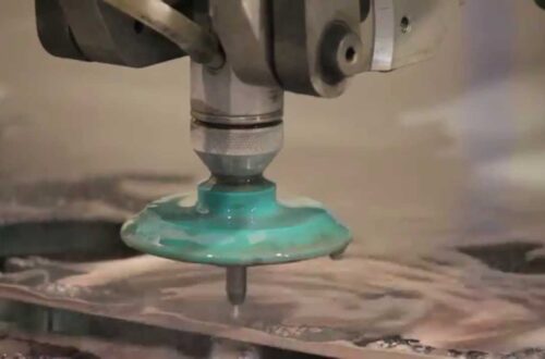
A CNC machine can hold remarkable geometry. Contours, radii, holes and cut-outs can be repeated part after part with a level of consistency that manual work struggles to match. But anyone who has run a glass fabrication floor knows the uncomfortable truth: the part that comes off the CNC table is not the part that goes on the truck.
Between the last toolpath and the finished component sits a chain of decisions and operations: edge selection, grinding, seaming, polishing, dimensional refinement and inspection. Each one can protect the accuracy the CNC delivered, or quietly erode it. This guide follows that chain from the drawing to the installation-ready component, with a focus on how geometry, tolerances and finish interact.
1. CNC Cutting Is Only the Beginning
It’s tempting to treat CNC cutting as “the fabrication.” The machine is the most visible and capital-intensive piece of equipment on the floor, and its output looks precise. But in a professional workflow, CNC machining is one stage in a controlled sequence, not the finish line.
Think about what a CNC operation actually delivers: the correct shape, in the correct position, with holes and cut-outs where the drawing says they should be. What it does not deliver on its own is the final edge condition, the final dimension after subsequent processing, the surface quality, or confirmation that the part meets the application it was ordered for.
Treating CNC as the end of the process leads to predictable problems:
- Parts that are geometrically perfect at the machine but undersized or out of tolerance after edgework.
- Edges that are technically finished but wrong for how the glass will be handled, assembled or exposed.
- Quality checks that confirm the programme ran correctly but not that the component is fit for use.
The shift in thinking is simple but significant: the CNC machine produces geometry; the full workflow produces a component. Everything that follows in this article builds on that distinction.
2. Reading the Digital Drawing Before Cutting
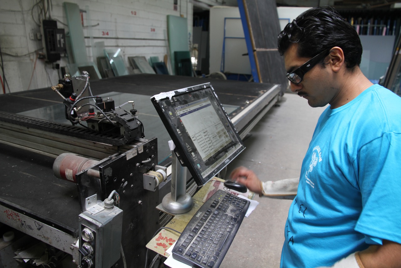
Quality in fabrication starts before the glass is on the table. The drawing and its associated digital files define what the machine will do and, just as importantly, what it won’t.
CAD/CAM files
The CAD file expresses design intent: the shape, size and features the customer or specifier wants. The CAM stage translates that into toolpaths, tool selection, cutting sequences and machine parameters. Errors at either stage carry straight through to the glass. A model that looks correct on screen can still produce problems if the CAM programming doesn’t reflect how the part will actually be finished.
Dimensions and tolerances
Every critical dimension should have a tolerance that reflects the finished part, not just the cut part. A tolerance that makes sense for a CNC operation in isolation may be unrealistic once edge processing removes material or the part is subject to further handling. Reviewing tolerances against the full process is one of the most valuable checks that can happen at this stage.
Radii and contours
Corner radii and curved contours affect both machining and edgework. Tight internal radii may limit tooling and the quality of the edge that can be achieved. Complex contours can make consistent edge removal harder, particularly where the edge profile changes direction. These are best identified on the drawing, not discovered at the polishing station.
Holes and cut-outs
Holes and cut-outs are critical for fit and assembly, and they are also edges. Their position, size, spacing from the glass edge and spacing from each other all influence both machinability and the finishing that follows. Hole location is a classic inspection point later in the process, so it needs to be unambiguous on the drawing.
Edge specifications
An edge specification that is vague, incomplete or missing is one of the most common sources of downstream disagreement. The drawing should state which edges receive which treatment, and whether any edges are exposed in the final installation. “Polished edges” and “polished exposed edges only” are very different instructions with very different costs and lead times.
Conflicts between design intent and fabrication requirements
The most expensive problems are those where the design intent and the realities of fabrication pull in different directions. Examples include a tolerance too tight for the specified edge finish, a feature too close to an edge to process safely, or a profile that can’t be produced consistently around a contour. A professional fabricator reviews the drawing for these conflicts before cutting, and raises them while they are still cheap to resolve.
3. What Happens to the Edge After CNC Cutting?
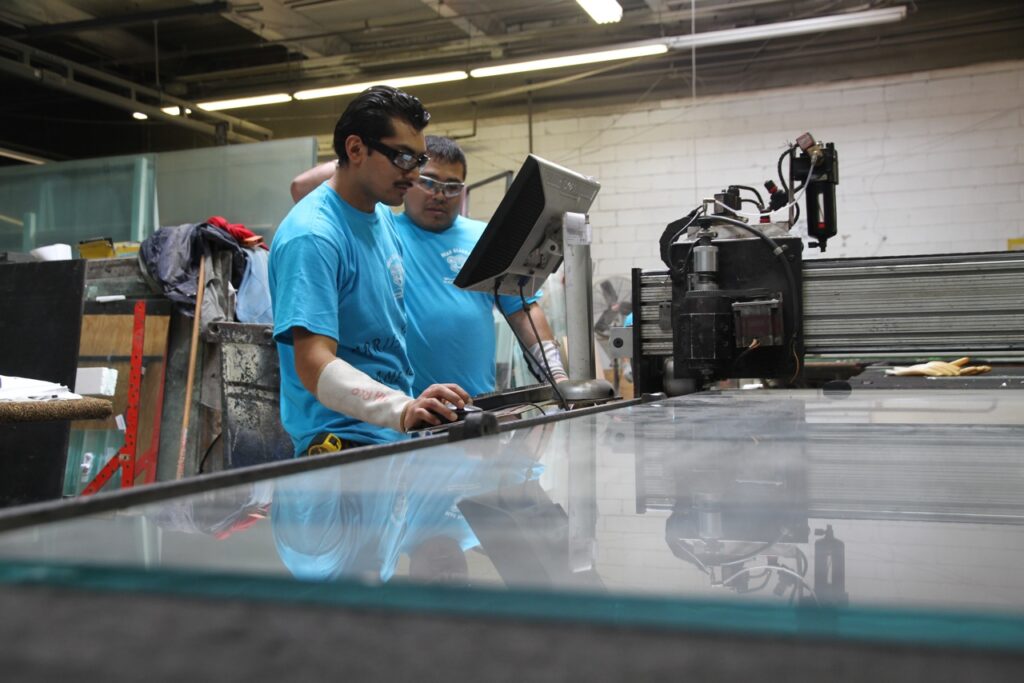
Once cutting is complete, the part moves from CNC-generated geometry to finished edgework. This transition is where much of the final quality is decided.
Raw and processed edges
A freshly cut edge is functional but not finished. Depending on the cutting method and tooling, it may carry marks, micro-chipping or a rough texture. That’s perfectly normal at this stage; it’s simply the starting condition for what comes next. Understanding what the edge looks like straight off the CNC lets the fabricator choose the right edge-processing route.
Grinding
Grinding removes material to establish the edge shape and bring the part toward its final dimension. It is the stage where an edge starts to take on a defined profile. Because grinding removes glass, it directly affects dimensions, which is why the allowance built into the CNC programme matters so much (more on that shortly).
Seaming
Seaming takes the sharpness off the edge. It’s a light treatment intended to make the glass safer to handle and reduce the risk of chipping, without turning the edge into a decorative feature. It is appropriate where the edge will be concealed, framed or otherwise not a visual element.
Polishing
Polishing refines the ground edge into a smooth, clear, finished surface. It is the treatment most associated with high-end architectural glass, where edges are visible and expected to look deliberate. Polishing improves both appearance and tactile quality, and it demands consistency, because an edge polished inconsistently is immediately obvious.
Dimensional refinement
Throughout grinding and polishing, material is being removed and the part’s dimensions are changing, even if only slightly. Dimensional refinement is the discipline of making sure those changes are planned, measured and controlled so that the part arrives at the finished size on the drawing rather than somewhere close to it.
4. Choosing the Right Edge Profile for the Application
This is one of the most important decisions in the workflow, and one that is often made too late. The right profile depends on how the glass will be used, handled, assembled and seen.
| Edge Profile | Typical Consideration |
|---|---|
| Flat Polish | Clean architectural appearance and exposed edges |
| Pencil Polish | Softer visual transition and tactile edge |
| Bevel | Decorative/architectural detailing |
| Chamfer | Controlled angled edge treatment |
| Miter | Applications requiring a precise angled edge relationship |
| Seamed Edge | Removing the sharpness of the cut edge while retaining a less-refined appearance |
Flat Polish
A flat polished edge presents a crisp, square, clear finish. It’s a natural choice where edges are exposed and the design calls for a clean, architectural look: frameless installations, shelves, panels and fixtures where the edge is part of the visual statement. Because it’s so clean, it also reveals any inconsistency, so process control matters.
Pencil Polish
A pencil polish rounds the edge into a smooth, softened profile. Visually, it creates a gentler transition from face to edge; physically, it feels more comfortable to the touch. It suits applications where people will see and handle the edge and where a softer look is preferred over a sharp, square one.
Bevel
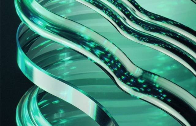
A bevel introduces an angled face along the edge of the glass, adding decorative or architectural detail. It’s chosen for its visual character, often catching and refracting light along the perimeter. Because it’s a feature rather than simply a finish, it needs to be specified clearly on the drawing, including how it should behave at corners and contours.
Chamfer
A chamfer is a controlled angled treatment of the edge. It’s used where a defined angled edge is wanted for handling, assembly or appearance reasons, without necessarily the decorative intent of a bevel. The angle and size should be specified deliberately, because chamfers that look similar on paper can behave differently in assembly.
Miter
A miter is an angled edge produced so that two pieces meet precisely, typically to form a corner. Here the edge is not a finish but a geometric relationship between components. Accuracy is critical, because small angular or dimensional errors show up directly in how the joint fits and looks.
Seamed Edge
A seamed edge removes the sharpness of the cut while retaining a less refined appearance. It’s an economical and practical choice where the edge will be hidden or protected, or where appearance isn’t a priority. It should be chosen deliberately, as a fit-for-purpose decision, not as a default.
The key point
Edge selection isn’t merely aesthetic. It has to correspond with the component, the handling requirements, the assembly method and the design intent. An edge that looks right on a sample but doesn’t suit how the part is handled, framed or installed will cause problems later, regardless of how well it was produced.
5. CNC Accuracy vs. Edgework Accuracy
Here’s where the article gets genuinely interesting for professionals: a part can have excellent CNC geometry and still fail its final specification. The machine did its job. The problem lies in what happened afterwards, or in what wasn’t planned beforehand.
Insufficient edge allowance
If the CNC programme doesn’t leave enough material for the edge processing that follows, the part can end up undersized once grinding and polishing are complete. Allowance has to be planned against the specific edge treatment, not assumed.
Inconsistent edge removal
Edgework removes material, and if the amount removed varies around the perimeter, from edge to edge or from part to part, dimensions drift. A part can end up out of square or out of size even though the CNC cut was accurate.
Dimensional changes during processing
Every processing step has the potential to alter dimensions. When these changes aren’t anticipated and controlled, the finished dimension differs from the programmed one.
Incorrect edge-profile selection
If the wrong profile is chosen, the part may meet its dimensions and still fail the requirement. It might look wrong, handle wrong, or not assemble properly. A correctly sized part with the wrong edge is still a non-conforming part.
Inadequate inspection
If inspection only confirms that the part was cut correctly, issues introduced later go unnoticed until the glass reaches the customer or the installation site, which is the most expensive place to find them.
Tolerance stack-up
Individual tolerances can each look reasonable, but their combined effect across several operations (or across several components in an assembly) can exceed what the final fit can absorb. Stack-up is easy to overlook when each operation is treated independently, and hard to fix once the parts exist.
The common thread: CNC accuracy is necessary, but it is not sufficient. Final quality depends on the whole chain.
6. Why Tolerances Matter After CNC Cutting
Achieving a programmed CNC dimension does not automatically mean the finished component will stay at that dimension after subsequent processing. Material is removed, edges are refined, and the part continues to change until the last operation is complete.
That’s why it helps to think of the process as a single, connected sequence:
CAD dimension → CNC cut → edge processing → final inspectionrather than as separate, independent operations. Each step inherits the result of the one before it and passes its own effects to the next.
In practice, this means:
- Tolerances should be defined for the finished part. If the final dimension is what matters, the tolerance needs to be expressed and controlled at that level, with the CNC and edge-processing stages working backwards from it.
- Allowances should be deliberate. The material left for edgework should be chosen for the specific edge treatment and process, not carried over from a previous job.
- Operations should be coordinated. Programming, cutting, edgework and inspection teams should be working from the same understanding of what “finished” means.
- Critical dimensions deserve extra attention. Dimensions that govern fit, assembly or visible alignment are the ones where small deviations matter most.
When tolerances are managed across the whole process, surprises at final inspection become rare. When each operation is treated on its own, they become routine.
7. Inspection: Where Fabrication Quality Is Actually Verified
A part isn’t finished until it’s been verified against what was ordered. Inspection is where the entire workflow is held to account, and it should be systematic rather than a quick glance.
Professional inspection typically covers:
- Overall dimensions: confirming length, width and any critical sizes against the drawing, ideally measured at the finished stage.
- Hole and cut-out locations: verifying positions, sizes and spacing, since these control fit and assembly.
- Edge profile: checking that the specified profile has been produced correctly and consistently, including at corners and transitions.
- Surface condition: looking for marks, scratches or other surface issues that may have occurred during processing or handling.
- Chips or damage: examining edges, corners and around holes and cut-outs, where damage is most likely.
- Visual consistency: confirming that edges and finishes look uniform across the part, and across multiple parts in the same order.
- Fit against drawings and templates: where applicable, checking the part physically against the reference to confirm it will fit as intended.
- Application-specific requirements: any additional requirements tied to how the component will be used or installed.
Notably, a great deal of this is about the finished edge, not just the glass dimensions. Inspecting only the size of a part misses much of what determines whether it’s acceptable. A thorough inspection process treats the finished component, edges included, as the thing being verified.
8. Common Fabrication Mistakes Between CNC and Edgework
Most problems in this part of the workflow come from a handful of recurring mistakes. They’re worth naming, because naming them is the first step to avoiding them.
Mistake #1: Treating CNC cutting as the final operation
When the cut is considered “done,” the downstream stages are treated as an afterthought. In reality, they define the final result. Plan for the full workflow from the start.
Mistake #2: Selecting the edge profile too late
If the edge profile isn’t decided until after cutting, the CNC programme can’t include the right allowance, and the fabrication route may be compromised. Decide the profile early so programming and processing can be aligned.
Mistake #3: Ignoring edgework when establishing tolerances
Tolerances set purely on CNC capability ignore the material removed and changes introduced later. Establish tolerances with the whole process in mind.
Mistake #4: Failing to account for the final application
A part that is perfect on the bench can be wrong in service. How the glass will be handled, assembled, exposed and installed should inform edge selection and finishing decisions from the beginning.
Mistake #5: Inspecting only the glass dimensions and not the finished edge
A dimensional check on its own can pass parts with poor edge quality, chips or inconsistent finish. Inspect the edge as carefully as the size.
Mistake #6: Assuming every CNC-cut edge should receive the same treatment
Different edges on the same part can have different roles: some are exposed, some are concealed, some are handled frequently, some are critical to assembly. Applying one treatment everywhere can waste cost on edges that don’t need it, or under-serve those that do.
9. The Professional Workflow
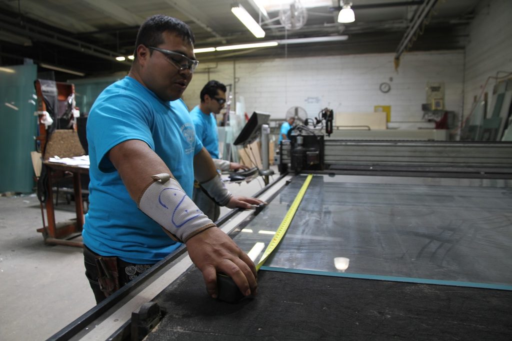
When all of the above is put together, a professional glass fabrication workflow looks like a controlled chain where each stage is informed by the ones before and after it:
DRAWING
   ↓
CAD/CAM PROGRAMMING
   ↓
CNC CUTTING
   ↓
EDGE PROCESSING
   ↓
POLISHING / FINISHING
   ↓
INSPECTION
   ↓
FINAL COMPONENT
A few points make this sequence work in practice:
- Information flows forward and backward. The drawing’s edge and tolerance requirements shape the programming; the realities of edgework feed back into the allowances and tolerances used earlier.
- Decisions are made early. Edge profile, allowances and critical dimensions are settled before the glass is cut, not after.
- Each stage has a clear handover. What the next operation needs is defined, and what the previous operation delivered is verified.
- Application drives the route. Where the glass is going and how it will be used determines which edges are finished, how, and to what standard.
10. The Final Question: Is the Glass Ready for Installation?
At the end of the process, one question matters more than any other: is this glass ready for installation?
Answering it honestly requires more than confirming that the CNC programme ran correctly. It means knowing that the geometry matches the drawing, that the edges are the right profile and finished to the right standard, that dimensions and tolerances hold after processing, and that inspection has verified the finished component against the requirements of its application.
It must be mentioned that glass fabrication quality isn’t determined by a single machine or a single operation. It is determined by how accurately the entire workflow is controlled, from the first review of the drawing to the final inspection of the finished edge.