Most waterjet problems on glazing projects are not cutting problems. They are handoff problems: a drawing that does not define the edge, a hole placed where the tempering furnace will punish it, a tolerance that ignores what happens after the cut, or a process chosen out of habit rather than fit.
This guide walks through the decisions that determine whether a waterjet-cut lite arrives on site right the first time. It is written for architects, glazing contractors, specifiers and fabrication engineers who already work with shaped glass and want to tighten the process around it.
In this guide
- Cut sequence and tempering: designing around the furnace
- Waterjet, CNC or laser: choosing the process
- Drawing and tolerance callouts that prevent RFIs
- Laminated and coated glass on the waterjet
- Feature limits: what geometry is buildable
- Edge quality and finishing by application
- From BIM model to finished lite
- Pre-submittal checklist
1. Cut Sequence and Tempering: Designing Around the Furnace
Fully tempered glass cannot be profile-cut after heat treatment. It will fail. That fixes the sequence for any shaped, notched or drilled lite that must be tempered: cut, finish the edge, then temper. Everything else in this section follows from that.
Dimensional responsibility is split across three stages
Cutting, edgework and tempering are often three separate steps, sometimes at three separate facilities. A tolerance on the final drawing is really a stack across all of them:
- Cut stage: positional accuracy, taper, kerf compensation
- Edge stage: material removed by arrissing, seaming or polishing, which changes the finished dimension
- Tempering stage: distortion, which changes flatness and can shift the profile
If the drawing does not say which stage owns which portion of the tolerance, disputes are settled after the fact. We recommend that dimensional expectations be stated for the finished, tempered part, with the fabricator working backward to allowances at each earlier stage.
What tempering does to a precise profile
Tempered glass moves. Roller wave, overall bow and edge kink are inherent to horizontal roller-hearth tempering and are limited by standards rather than eliminated. For shaped lites this has practical consequences:
- Flatness is not free. A lite that is dimensionally perfect after cutting can still be out of plane after the furnace. Where fit depends on flatness (frameless assemblies, point-fixed systems, flush inset panels), specify flatness limits and confirm the tempering facility can meet them for that geometry and thickness.
- Orientation in the furnace matters. Long, narrow lites and lites with large cut-outs behave differently depending on which direction they travel. Involve the tempering facility early on unusual shapes.
- Cut-outs and notches concentrate stress. Heating and quenching are not uniform around an inside corner. Sharp internal corners are a leading cause of breakage in the furnace and of later spontaneous failure.
Design rules that protect the lite
The values below are commonly used starting points. Actual limits depend on thickness, glass type and the tempering facility’s equipment, so confirm with the facility before locking a design.
- Hole diameter: not smaller than the glass thickness
- Hole-to-edge distance: generally a minimum of about two times the glass thickness
- Hole-to-hole spacing: generally at least two times the thickness
- Hole-to-corner distance: more conservative, often several times the thickness
- Inside corners and notches: always radiused, never sharp
Also keep in mind that heat-treated glass is subject to spontaneous breakage from nickel sulfide inclusions in fully tempered glass. Where the consequence of breakage is high (overhead glazing, high-occupancy areas), heat-soak testing is a specification decision, not an afterthought.
Compensating for post-temper movement
Whether to compensate the cut geometry for expected movement is a judgment call that depends on the application. For most architectural work, we do not recommend adding arbitrary compensation. We recommend controlling what can be controlled (edge condition, feature placement, orientation) and specifying realistic flatness and dimensional limits for the finished part. Where a fit is truly critical, a pilot lite through the full process sequence gives real data instead of assumptions.

2. Waterjet, CNC or Laser: Choosing the Process
No process wins across the board. The right choice depends on geometry, thickness, edge requirement and volume.
| Consideration | Waterjet | CNC (diamond tooling) | Laser |
|---|---|---|---|
| Complex internal profiles | Excellent, including tight nested shapes | Limited by tool diameter | Limited use on thick architectural glass |
| Thick and laminated glass | Strong; cuts laminated in one pass | Strong on monolithic; laminated needs care | Generally not the tool for thick architectural lites |
| Inside radius | Small radii possible (governed by kerf and stress limits) | Governed by tool radius | Fine features on thin or specialty glass |
| Edge as-cut | Matte, satin texture; usually needs finishing for exposed edges | Ground or polished finish achievable in one setup | Process-dependent |
| Thermal effects | None (cold process) | Minimal | Heat input is a concern in most glass applications |
| Best fit | Irregular shapes, cut-outs, thick and laminated stock, low-to-mid volume | Straight or simply shaped edges needing a finished polish, repeatable production | Thin, specialty or precision glass where the process suits the substrate |
How we decide
- Choose waterjet when geometry is complex, when inside features are tight, when the glass is thick or laminated, or when no tool-access limitation should constrain the design.
- Choose CNC when the edge must come off the machine finished, when the shape is achievable with a tool radius, or when production volume favors it.
- Combine processes when it makes sense. A common approach is waterjet for the profile and holes, followed by CNC or hand finishing for exposed edges.
- Do not force a process to fit a drawing. If a design only works with one, tell the fabricator early.
Cost follows the same logic. Waterjet has low tooling cost and handles one-offs well, but cycle time rises with cut length and thickness. CNC can win on throughput when the geometry allows.
3. Drawing and Tolerance Callouts That Prevent RFIs
Fabricators build what the drawing says. Gaps in the drawing become RFIs, and RFIs become schedule risk. For waterjet-cut lites, we look for the following on the drawing:
Required on every shaped lite
- Glass type and thickness, including build-up for laminated and IGU components
- Heat-treatment requirement: annealed, heat-strengthened, or fully tempered, plus heat-soak if required
- Overall dimensions with tolerance, stated for the finished part
- Datum scheme: which edges or holes are the reference, so tolerances are not stacked chain-style from an arbitrary corner
- Edge condition, per edge: as-cut, arrissed, seamed, ground, or polished. Do not assume one edge spec applies to the whole perimeter
- Hole and cut-out dimensions with position tolerance relative to the datum
- Minimum radii on all inside corners, called out explicitly
- Applicable standards for the glass, heat treatment and safety glazing performance
Tolerance tips
- Tolerance where function demands it, and only there. Tightening every dimension raises cost and rejection without improving the installed result.
- Distinguish fit-critical from cosmetic dimensions. A hole receiving a fitting needs tighter position control than the outer profile of a feature panel with generous reveals.
- State how the tolerance is measured. A callout with no inspection method invites disagreement at receiving.
- Mark surface requirements. Fritted, coated or patterned lites need a defined orientation, and the cut should be referenced to the pattern if alignment is required.
Common drawing gaps that trigger RFIs
- Unspecified edge finish on exposed edges
- Sharp inside corners on notches
- Holes too close to edges or corners for the thickness
- No indication of which face receives the coating or frit
- Conflicting dimensions between plan, elevation and detail views
- Tolerances that silently conflict with process capability
4. Laminated and Coated Glass on the Waterjet
Laminated glass
Waterjet cuts laminated glass in one pass, which is a major advantage for shaped laminated lites. The engineering concerns are specific:
- Piercing risk. Piercing puts the most stress on the assembly. Low-pressure ramped pierces and lead-ins placed in scrap material protect the interlayer bond and the finished edge.
- Interlayer behavior. PVB, SGP and other interlayers respond differently to the cutting stream. Stiffer interlayers used in structural applications can behave differently at the cut edge than standard PVB. Confirm the process with the specific interlayer.
- Edge exposure to water and abrasive. The cut leaves the interlayer exposed at the edge. Water and abrasive contamination, and prolonged exposure to moisture at the edge, can affect long-term edge appearance and bond. Prompt cleaning and drying, and appropriate edge sealing for exposed applications, protect the assembly.
- Sequence. For heat-treated laminated lites, the plies are typically processed, heat-treated and then laminated. Waterjet cutting of an already-laminated, heat-treated assembly is not a substitute for cutting plies before treatment. Define the sequence early.
- Offset between plies. Cutting through both plies from one side produces a consistent edge, but any ply offset in the lay-up needs to be specified.
Coated glass
Coatings add a layer of process control:
- Soft-coat low-E and similar coatings are sensitive. Water, garnet slurry and handling contact can damage or stain the coating. Protective film and controlled process handling are essential.
- Coating orientation. Cut with the coated surface protected, and confirm the intended coating position (surface number) in the final assembly.
- Edge deletion. Where coatings must be deleted at the edge for sealing or durability, plan that step. It is a separate operation and it affects the sequence.
- Pyrolytic versus sputtered coatings. Their durability, treatment requirements and handling sensitivities differ. Match the process plan to the coating type and the supplier’s guidance.
- Ceramic frit and printed patterns. Alignment between cut and pattern is a registration problem, best solved with vision-assisted positioning and a clear datum. Also confirm whether the frit is applied before or after cutting.
For both laminated and coated lites, a test cut on offcut material from the same lot is inexpensive insurance before committing a full run.
5. Feature Limits: What Geometry Is Buildable
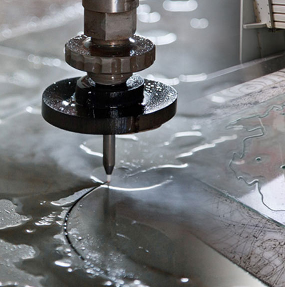
Waterjet is forgiving, not limitless. Buildability is set by kerf, stream behavior, glass strength and downstream processing.
Inside radii
The absolute limit of the stream is small, but the practical limit is set by glass stress and later heat treatment. A radius the machine can cut may still be a poor idea because it concentrates stress. As a design rule, use the largest inside radius the design can tolerate, and never a sharp corner on a lite that will be tempered.
Narrow webs and slender features
Thin bridges of glass between cut-outs are fragile in handling, on the table and in the furnace. Keep webs proportionate to the thickness of the glass. If a design needs a slender element, discuss it with the fabricator before it is drawn, because it may need to be handled and supported differently or redesigned.
Hole and cut-out placement
Follow the hole-to-edge, hole-to-hole and hole-to-corner guidance in Section 1. Where a design pushes those limits, expect lower yield and higher risk.
Tight nesting
Aggressive nesting improves yield but reduces the material left between parts. On thin glass or complex shapes, insufficient web between nested parts risks movement, cracking and dimensional error. Sequence matters as much as layout: cut inside features first, then outside profiles, and support the sheet so parts do not shift.
Size and thickness ranges
Maximum lite size is governed by table size, handling capability and, for heat-treated glass, furnace size and capacity. Thickness affects cut speed, taper and achievable tolerance. Very thick glass slows the cut and demands more compensation. Confirm the full envelope for size, thickness and treatment together rather than each in isolation.
6. Edge Quality and Finishing by Application
A waterjet edge is satin and slightly textured. That is fine for a concealed edge in a channel. It is usually not what a client expects on an exposed edge at hand height.
Match the edge to the use
| Application | Typical edge approach |
|---|---|
| Concealed in a frame or channel | As-cut or lightly arrissed, depending on safety and handling |
| Exposed, low-contact (feature walls, back-painted panels) | Seamed or ground, with attention to appearance |
| Exposed, high-contact (railings, partitions, furniture, countertops) | Ground and polished for safety, touch and appearance |
| Structural or point-fixed | Edge quality specified for strength as well as finish; heat-treated glass edges are strength-critical |
| Tempered lites | Edge finished before tempering, since tempering locks in the condition |
Edge quality matters for strength
Edge flaws are where glass breaks. Poor edge condition lowers effective strength and is a known contributor to breakage in service and in the furnace. For lites that will be tempered or heat-strengthened, the edge should be finished to a defined level before treatment. Specify it. Do not leave it to interpretation.
Visual quality
Exposed edges on laminated glass show the interlayer, and any offset or discoloration is visible. Where appearance is critical, review a finished edge sample before production.
7. From BIM Model to Finished Lite
Shaped glass is a digital workflow, and the quality of the handoff determines the quality of the result.
File formats and geometry
- 2D cut files (DXF, DWG) are the standard input for cutting. 3D models (STEP, IFC, native Revit or Rhino) carry context but need to be translated into clean 2D profiles.
- Clean geometry cuts better. Closed profiles, no overlapping lines or duplicate entities, arcs represented as true arcs instead of dense polylines, and no stray geometry.
- Layer discipline. Separate outer profile, inside cut-outs, holes, and reference or notation layers. Clear layers reduce interpretation errors.
- Units and scale. State units. Confirm scale in the file against the drawing.
Reconcile the model and the drawing
A model and a drawing that disagree are the fastest route to a wrong lift. Establish which document governs, and have any conflict resolved in writing before cutting.
Tolerance stack-up
Glass does not sit in isolation. Framing tolerances, structural movement, sealant joints and installation tolerances all combine with the lite’s own tolerance. Reviewing the stack-up with the fabricator at design stage tells you whether the specified tolerances are actually achievable and whether the joint design has room for them.
Involve the fabricator early
The largest savings come before the drawings are issued. An early review typically surfaces:
- Features that the process or the furnace cannot support
- Cheaper geometry that achieves the same design intent
- Thickness and glass-type choices that reduce risk
- Realistic lead times, particularly for laminated, coated or heat-soaked glass
- Sample and mock-up requirements
Mock-ups and first-article approval
For complex or high-visibility work, approve a first article through the complete process, including edgework and heat treatment, before releasing the full run. It catches problems at the cost of one lite instead of one hundred.
8. Pre-Submittal Checklist
Before shaped-glass drawings go out, confirm:
- Glass type, thickness, build-up and heat treatment are defined
- Tolerances are stated for the finished part and tied to a datum scheme
- Every edge has a defined finish
- Inside corners are radiused; radii are called out
- Hole-to-edge, hole-to-hole and hole-to-corner distances suit the thickness
- Coating position, frit orientation and any edge deletion are shown
- Laminated build-ups, interlayer type and edge exposure conditions are stated
- Applicable standards are listed
- The model and drawing match, and the DXF or DWG is clean
- Sequence (cut, edge, temper, laminate, assemble) is agreed with the fabricator
- First-article or mock-up requirements are defined
Work with Bear Glass
Bear Glass supports architects, builders, glazing contractors and commercial specifiers across New York and New Jersey. The earlier we see a shaped-glass design, the more we can do about cost, schedule and risk. Send us your drawings and models before they are finalized, and we will review geometry, sequence, edge requirements and tolerance stack-up with you.